Adding Remote Control of the Stereo Receiver to PlayerPi via Brilliant
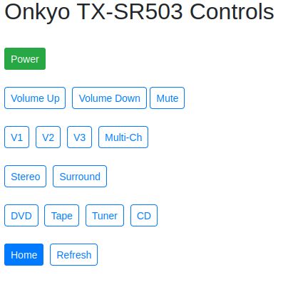
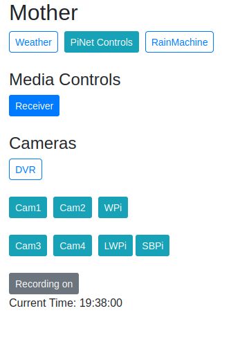
Image: The screen served by Brilliant on my local network.
(PlayerPi? Brilliant? wha?) 1 Photo gallery below.
It is possible to control devices using IR with a Raspberry Pi running Raspbian.
In the old days if you wanted to work with IR remote control devices in Linux, you used LIRC. It was a workable system, but one I found particularly complicated.
These days driver support for IR receivers and emitters is built-in to the Linux kernel, and can be utilized pretty easily. Raspbian is a version of Debian Linux customized for ease-of-use by the Raspberry Pi market, so using the Pi should just work.
My most recent attempt uses this modern kernel-based method of interfacing with IR hardware. Finding out how to use it required the normal investigation, but was doable.
I'm going to share here the steps I took to get a working IR remote control system. In my use-case here, I only need to control one device, so I'm building the IR receiver on a breadboard. It is just temporary. Once I have the codes, then I use those codes to control my receiver. In the end, the final hardware configuration is an IR emitter attached to PlayerPi.
I'm going to try to format this in a compact manner, which means I'm not going to illustrate every single step with a graphic. You will be able to follow, but you may have to fill in details with your own experience, either prior or contemporary.
In a nutshell, there are two commands that got me where I was trying to go:
ir-keytable with several steps helped me gather codes.
ir-ctl -S to send the discovered hex codes.
Steps to take with a Raspberry Pi
- Add a IR receiver so you can read remote signals
a. add the hardware
b. add the firmware configuration (/boot/config.txt) - Add an IR emitter so you can send them. Jump there
a. add the hardware
b. add the firmware configuration
Step 1 - Add an IR Receiver
In order to read the codes emitted by your gear's remote control, you need to hook up an IR receiver and listen for them.
There are many options when it comes to components for both the IR receiver and the transmitter.
I am using a receiver built around the VS1838B, which looks like this: Amazon link

There is also the TSOP38238. Adafruit sells this one, so you know it's going to be OK. It looks like this: Afafruit link

As always, read the docs. You should carefully identify which leg is power in, which is ground, and which is signal.
Connect the VCC (power) leg to 5VDC. 5 volts is commonly recommended.
Connect the ground to ground.
Connect the signal leg to one of the GPIO pins on your Pi. GPIO Pinout
Edit /boot/config.txt. Use 'sudo'. Save. Reboot.
You need to add this line to /boot/config.txt:
dtoverlay=gpio-ir,gpio_pin=14
Of course, the gpio_pin number has to match the pin you have attached to the signal leg of the IR receiver.
lsmod | grep gpio
You should see 'gpio_ir_recv'.
cat /proc/bus/input/devices
You should see several lines, one of them ending with '/rc/rc0/input0' The 'rc0' is the most important piece of information out of all that output. It could be 'rc1'. They seem to get swapped now and then, so when 'rc0' doesn't work, try 'rc1' before giving up.
See if ir-keytable is installed. Type it and you'll know.
If it's not installed, type:
sudo apt install ir-keytable
Now type ir-keytable again. You should be able to find 'rc0' or 'rc1' in the output.
Tell ir-keytable to load all of the protocols.
sudo ir-keytable -p all
Now you're ready to capture some codes.
ir-keytable -t -s rc0
Note: if you saw 'rc1' before, then use 'rc1'. Most times it's going to be 'rc0'.
Aim your remote control at the IR receiver and press a button. You should immediately see some new output on the screen. Press different buttons to see what the differences are between the output. Those differences are the data specific to that button. You'll want to refer to that later, so pay attention now.
You are done setting up the IR receiver. Now let's look at getting the IR transmitter (emitter) working.
Step 2. Add an IR Emitter
You want a IR LED emitter that works at 38Khz. There are IR emitters available that use different carrier frequencies. Just make sure the one you choose includes 38Khz in its operating range.
There are a lot of options when it comes to adding the IR emitter. I cheated. I used a 'remote emitter' from my junk collection. It came with the Logitech Harmony Hub that died recently. This part had never been used. But because I never throw anything away, when I needed an IR Emitter, I had . . . well, two actually.
This emitter has a nice case with a cord. It might have resistors in series, but I was not able to verify it visually. I used my bench power supply to determine the working parameters of LED. Turns out it has three LEDs and had a decent amount of brilliance around 3VDC drawing around 20mA. I used my cellphone camera to see the luminance. Not very scientific, but it worked.
I ended up not using a current-limiting resistor at all, and it's working fine. NOTE: In all the text below, I'm writing as if you are going to use a current-limiting resistor. Don't be confused by that. If you're not, just leave it out.
If you can find one, you can use a commercially made emitter like I did. They are available to buy on Amazon or Adafruit. If not, you can roll your own. Just select the proper resistor to put inline so you don't pop it, and figure out how to hide it from sight.
The circuit that makes the IR emitter work utilizes a NPN transistor and a 200Ω resistor as well as the IR emitter LED and its current-limiting resistor. Selecting the current-limiting resistor is a convoluted topic of its own.
I suggest you read here and here.
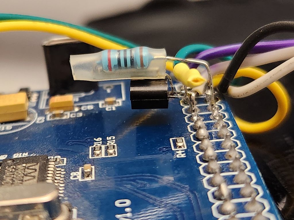
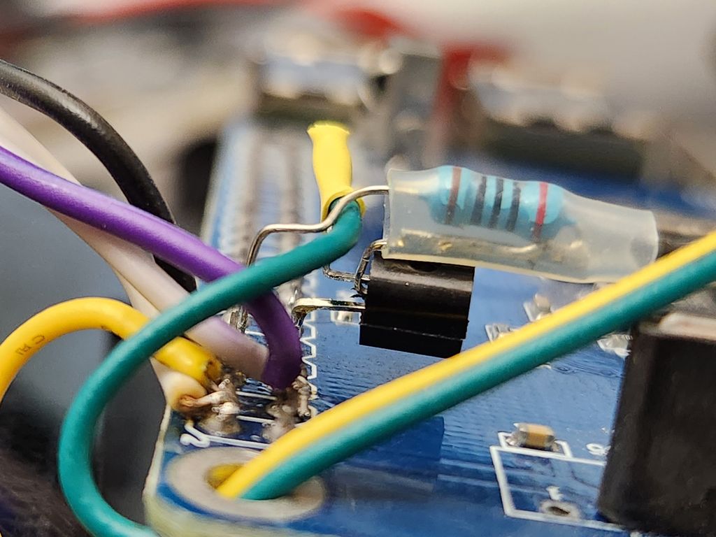
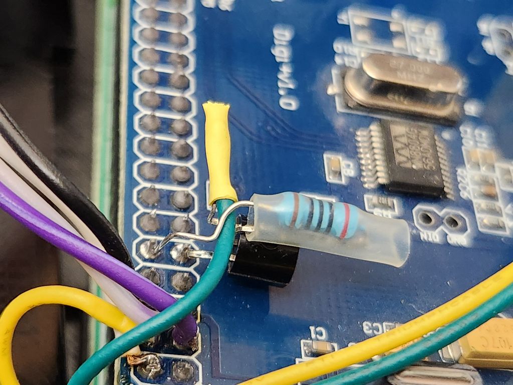
Be aware, the Gordon Turner blog in the link above shows the transistor wired backward from how I did it. He has the collector on the negative side of the power supply, and the IR LED on the emitter side tied in series to the + 5VDC. I followed that example initially (seen in the photos in the gallery below), but was bothered by it. After a lot of investigation, I rewired mine to put the collector on the positive side, and the emitter, current limiting resistor and IR LED going to ground.
I have used both a 2N222 and a BC547 transistors for this application. Both worked fine. I bought a nice 30-type variety kit off Amazon. No problems.
Choose a GPIO pin and then wire it up like this:
The 200Ω resistor goes between your chosen GPIO pin and the BASE leg of the transistor.
The negative (shorter) leg of the IR LED is attached to ground.
The positive (longer) leg of the IR LED connects to one lead of your current-limiting resistor (or not).
The other lead from the current-limiting resistor (or not) goes to the Emitter leg of the transistor.
The collector leg of the transistor goes to +5VDC.
How you decide to physically connect all this is entirely up to you. Crimp it, solder it, duct tape it, your choice.
Edit /boot/config.txt. Use 'sudo'. Save. Reboot.
You need to add this line to /boot/config.txt:
dtoverlay=gpio-ir-tx,gpio_pin=15
Of course, the gpio_pin number has to match the pin you have attached to the BASE leg of the transistor.
After saving and rebooting you can use this command to make sure the driver overlay is loaded:
lsmod | grep gpio
greg@playerpi:~ $ sudo lsmod | grep gpio
gpio_ir_tx 16384 0
Testing for signal
Most cellphone cameras will allow you to see the LED light up when you send a test code. Mine does. Yours probably does too. So that's a handy test tool.
My little IR receiver board has an LED on it that flashes when it receives proper pulses on the right carrier frequency. That's helpful.
Of course, the real proof is in the pudding, and in this case, the pudding is seeing a device respond to a sent IR code. All my stuff is done in Python, so in Python I wrote these lines:
1       ##  RECEIVED AN IR COMMAND PACKET
2            if InCmd == 'remctl':
3                ircmdpikl = conn.recv(1024)
4                ircmd = pickle.loads(ircmdpikl)
5                ircmdcode = config.get("onkyo-tx-sr503",ircmd)
6                if ircmdcode != "blank":
7                    subprocess.call(["/usr/bin/ir-ctl", "-S", ircmdcode], stdout=subprocess.DEVNULL)
Of course that's not all the code. It's just the part that matters.
I use a home-brew browser-based interface to interact with all the parts of my PiNet. I created a screen (seen at the top of this post) for the Onkyo receiver.
- I touch a button and Brilliant receives a command.
- Brilliant hands the desired action to socketClient.py, which packs it up in a serialized bundle using the Python pickle module.
- Brilliant's socketClient.py sends that over a network socket to PlayerPi.
- PlayerPi has socketIRHost.py running as a systemd service. It's listening.
- Brilliant prompts PlayerPi with the string: 'remctl'.
- PlayerPi gets ready to catch the package.
- Brilliant sends the pickled command.
- PlayerPi captures the pickled command packet and disassembles it.
- PlayerPi compares the command to a list in a configuration file (.conf). If it finds a match, it returns a valid hex IR code.
- PlayerPi then uses the Linux ir-ctl command to make the IR LED broadcast the code.
How you get Linux to tell ir-ctl to send the code is entirely up to you. I don't expect anyone to do it just like I do. You may if you wish, but there are lots of ways to get that done. And that, my friend, is the point. You decide. You do it your way.
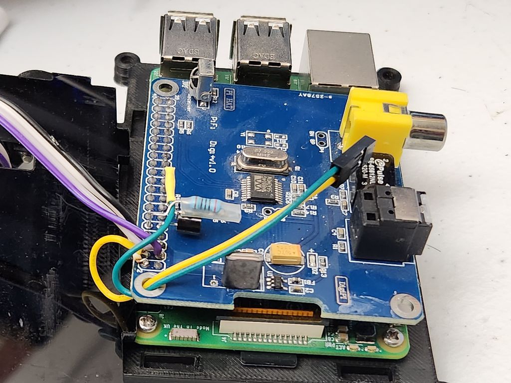
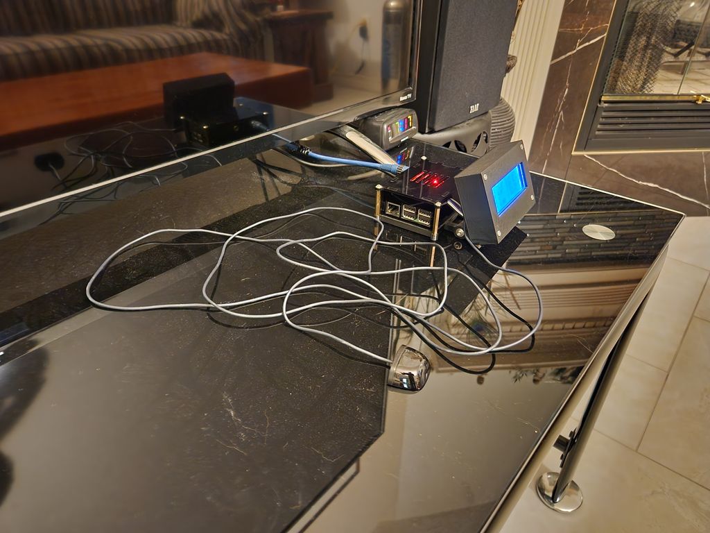
In the following gallery of photos you can see the way I mounted my components on top of the HiFi audio hat which sits on top of the GPIO header on PlayerPi. Again: these were shot after the first wiring. I've since swapped the ins and outs.
Also, there are two shots of screens: Mother, which is my home screen, and then the screen for the Onkyo receiver. These are served by NGINX, Flask and Jinja2 on Brilliant.

This little experiment is completely fulfilling a real need for me. So without qualification I can say this is a thing that works!.

-
PlayerPi and Brilliant are the hostnames of two of my computers. PlayerPi is a Raspberry Pi with a HiFi hat, and running MPD. There's an optical cable from the hat to the Onkyo receiver. Brilliant is the i3 Intel Ubuntu machine that runs allApp.py, which is the backend to the local-only browser interface where all my home controls are found. ↩